Rolling Ohms in ENPH 253
Every summer the UBC Engineering Physics ENPH 253 course drops four-person teams into an intense six-week sprint: design and build a fully autonomous rescue robot that frees stranded “pets” (plushies) and returns them to a safe zone. Our Rolling Ohms bot line-tracked around the course, scooped friendly pets with a servo arm, and flung hostile ones with TPU flywheels spinning at ~50 km/h tips to clear an eight-foot arc.
Embedded Architecture
- FreeRTOS twin-ESP32 stack: One ESP32 “brain” orchestrated the drive, arm, and launcher tasks (
src/complete_robot/complete_robot_main.c), while a second board handled the IR beacon alignment and high-speed telemetry. Everything ran as FreeRTOS tasks so the PID line follower, arm inverse kinematics, and shooter safety interlocks could run concurrently without starving each other. - Line following PID: The
lib/tasks/drive_system.ctask reads dual IR reflectance sensors at 10 ms intervals and applies a PID correction around a 900 mV midpoint. When both sensors see floor, we fall back to a slow spin using the last-known line side—this saved countless runs during testing. - Pet sweep and grab: We wrapped the arm driver in
lib/logic/sweep.cso the robot can arc the base servo across a sector, watch for IR voltage dips from plushies, and then execute a coordinated reach/close/retract sequence before returning to FreeRTOS idle. - Board-to-board comms:
lib/serial_comm/serial_protocol.cpackages control frames into framed JSON over UART so either ESP32 (or the Python desktop app) can push PID gains, arm poses, or fire commands. Each packet is mutex guarded to keep telemetry streaming while commands update. - Python telemetry + teleop:
python/serial_monitor_gui.pyis our Tkinter cockpit. It auto-discovers serial devices, streams JSON into live charts, and exposes sliders for servo angles, IK X/Y/θ targets, and shooter toggles. During integration we ran this alongside the FreeRTOS telemetry task that emits sensor voltages, basket lock status, and PID internals every 100 ms. - Beacon DSP: The beacon tracker ESP32 samples the IR photodiode at 50 kS/s and runs an arbitrary-frequency Goertzel transform (
src/ir_reciever/reciever_main.c) to extract the 1 kHz rescue beacon versus 10 kHz noise. We steer by maximizing the 1 kHz magnitude and mirror the results to a DAC channel for quick scope debugging.
PCB Stack

Three KiCad boards (fabricated at JLCPCB) tied the robot together:
- Brain board: Hosts an ESP32-WROOM module, pluggable headers for every peripheral (IR sensors, MG90S servos, beacon photodiodes, shooter FET), level shifting, and an event-button interface. In hindsight I should have added current-limiting resistors on the servo optocouplers and kept the noisy 5 V ring away from the board perimeter.
- H-Bridge board: A four-channel MOSFET stage with optocoupled logic, a BJT clamp, and high-side drive transistors so we could source current into 12 V motors without toasting GPIO. Missing current-limit resistors on the optocouplers meant extra rework, but once fixed the FreeRTOS
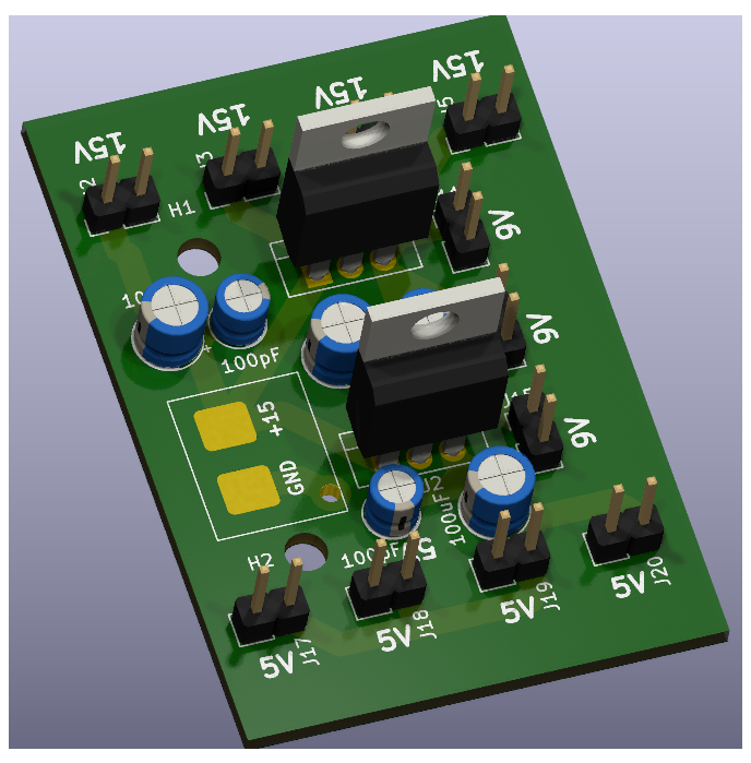
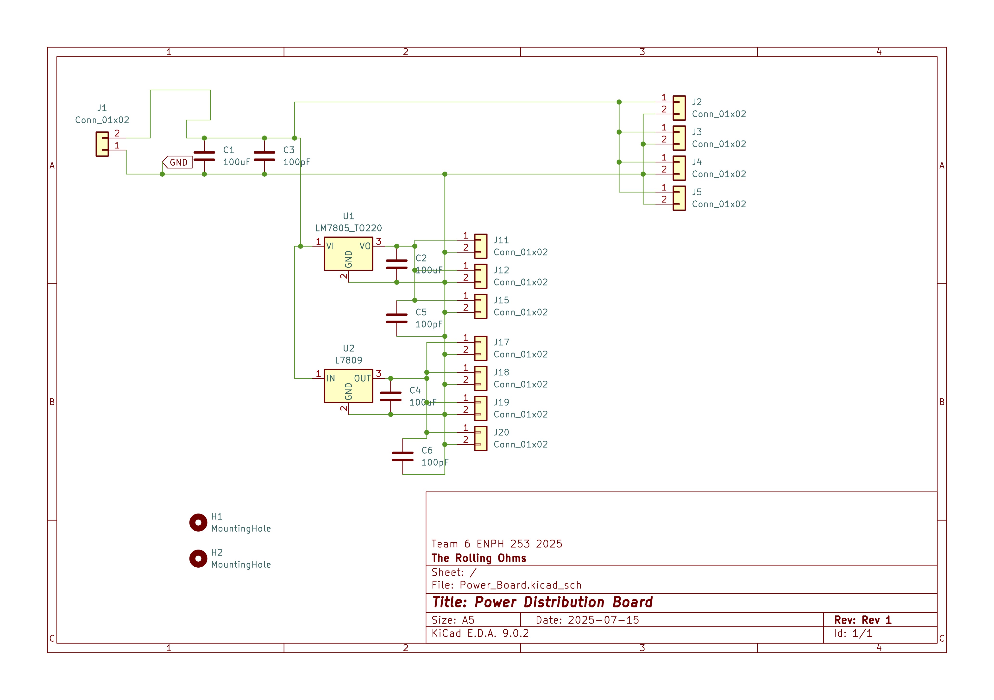
h_bridgedriver could ramp both sides with mutex-protected LEDC updates. - Power distribution board: Breaks a 15 V LiPo into fused rails for logic, arm, and launcher subsystems. I packed the caps too tightly, which made heatsink installation painful and forced a Dremel pass before competition day—next rev gets more copper pour and clearance.
Repository links:
Mechanical Systems
![]()
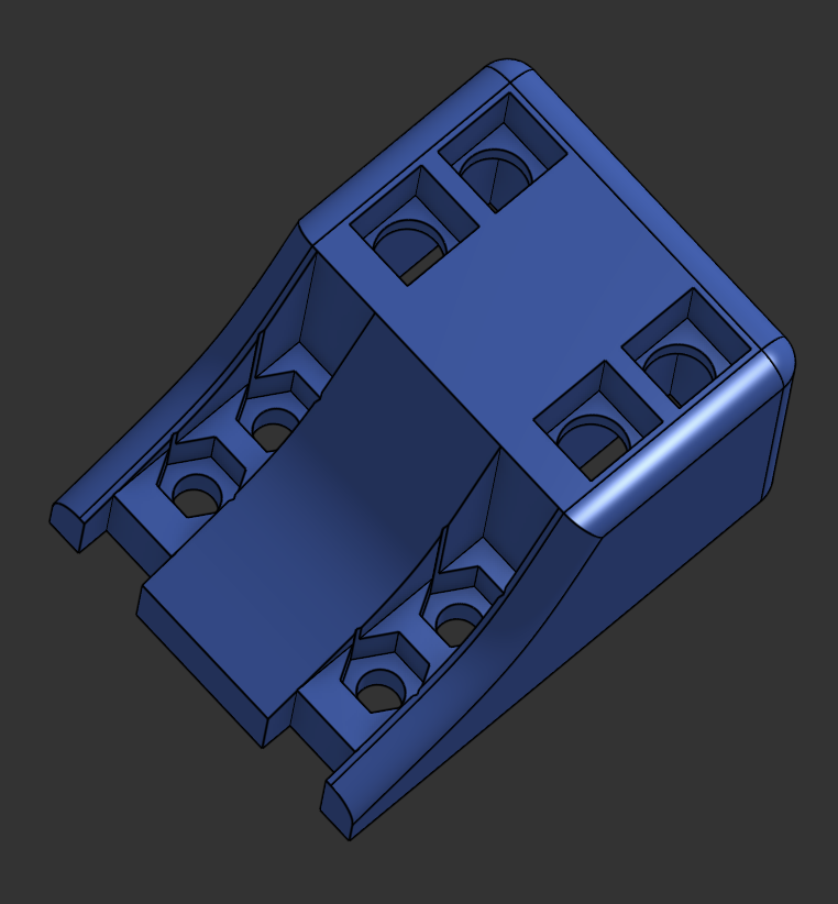
We modelled every subsystem in OnShape and split fabrication across laser-cut PMMA, milled aluminum brackets, and 3D printed TPU/PLA. Highlights:
- Dual shrouds shielded the IR line sensors and the beacon photodiodes from arena lighting, tightening our ADC noise spread (and justifying the low-pass filtering in firmware).
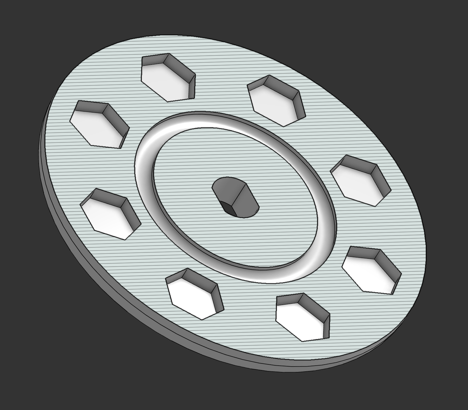
- The flywheel launcher uses TPU wheels with embedded brass nuts and steel bead pockets. We paused prints to insert the weights, then sealed them to add rotational inertia and self-balance—only two PWM setpoints (“off” and “all in”) survived testing, so the firmware’s high-resolution control wound up acting like a smart relay.
- The arm combines 3D printed links with laser-cut Delrin grabbers. A custom MOSFET stage handles the flywheel enable, while indexing plates let us re-angle the launcher between rounds without reprinting parts.
Debug Notes
- Brain board servos initially drew GPIO current directly; bodge-added resistors kept the ESP32 alive.
- Routing 5 V around the brain’s perimeter invited EMI into the line sensors—burying that rail or adding ground guard traces is on the re-spin list.
- The power board’s dense packaging blocked electrolytic caps and clashed with our FET heatsinks.
- H-bridge optocouplers required series resistors after smoke test number one. At least the pads were accessible.
Lessons Learned
- KiCad across multiple boards needs rigorous interface reviews (and printed 1:1 plots) before ordering.
- Always current-limit LEDs, optos, and anything that might meet 3.3 V silicon.
- Assume future-you will forget details—document everything and design for idiot-proof debug.
- Fasteners dominate build time; design brackets that snap or slot together to stay on schedule.
- Tooling matters: the Python telemetry app saved hours of guessing and let the whole team monitor states in real time.
- Peer design reviews catch silly mistakes (like missing opto resistors) before JLC makes them permanent.
- Add generous mounting holes to every PCB and leverage 2D manufacturing when possible for quick iterations.
- Hardware you can buy (like proven H-bridges) is often worth the money; custom power electronics eat time and nerves.
- Team success came from over-communicating between firmware, electrical, and mechanical—siloing slowed us more than any technical hurdle.